In this complete CNC machining design guide, Elimold has compiled basic and advanced design practices and tips to help you achieve the best results for your custom parts.
CNC machining is a subtractive manufacturing technique using various high-speed rotating cutting tools to remove material from solid blocks and produce parts based on CAD models. Both metals and plastics can be CNC machined.
CNC machined parts have high dimensional accuracy and tight tolerances and are suitable for mass production and one-off jobs. CNC machining is currently the most cost-effective way to produce metal prototypes.
1. What are the main limitations of CNC design?
CNC offers great design flexibility but also has some limitations. These limitations are related to the fundamental mechanics of the cutting process, mainly involving tool geometry and passage.
(1)Tool geometry
The most common CNC cutting tools (end mills and drills) have cylindrical shapes and limited cutting lengths.
The tool geometry is transferred to the machined part as the material is removed from the workpiece. This means, for example, that the inside corners of a CNC part always have a radius, no matter how small the cutting tool is used.
(2)Tool access
To remove material, the tool approaches the workpiece directly from above. Features that cannot be accessed this way cannot be CNC machined. There is one exception to this rule, though: undercuts. A good design practice is to align all features of the model (holes, cavities, vertical walls, etc.) to one of the six cardinal directions. However, consider this rule a recommendation rather than a limitation, as 5-axis CNC systems offer advanced work-holding capabilities.
Tool access is also an issue when machining features with large depth-to-width ratios. For example, to reach the bottom of a deep cavity, you need a tool with an extended reach. This means a wider range of motion for the end effector, which increases machine chatter and reduces achievable accuracy.
It simplifies production if you design a part that can be CNC machined using the tool with the largest possible Diameter and shortest length.
2.CNC Design Guidelines
A challenge often encountered when designing parts for CNC machining is that there are no industry-wide specific standards. Manufacturers of CNC machine tools and tools are constantly improving their technical capabilities and expanding the limits of what is possible. The following table summarizes recommended and possible values for the most common features encountered in CNC machined parts.
(1). Cavities and pockets
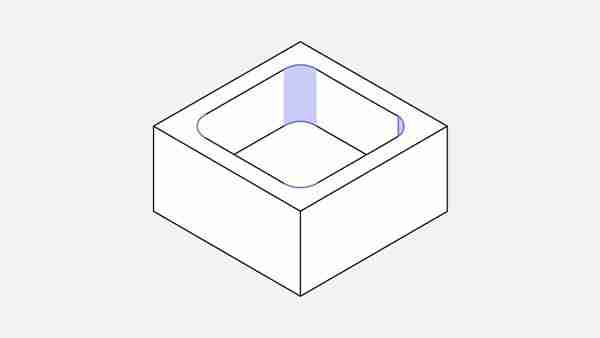
(usually 3-4 times their diameter). When the depth-to-width ratiRecommended cavity depth: 4 times cavity width
End mills have a limited cutting lengtho of the cavity is small, tool deflection, chip evacuation, and vibration become more prominent. Limiting the depth of the cavity to four times its width ensures good results. Consider designing a part with variable cavity depth if a greater depth is required.
Deep Cavity Milling: A cavity with a depth greater than six times the tool diameter is considered deep. Using special tools (maximum depth: 35 cm, 1-inch diameter end mill), tool diameter-to-cavity depth ratios of up to 30:1 can be achieved.
(2). Inside edge
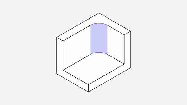
vertical corner radius
Recommended: ⅓ times the cavity depth (or more)
Using the recommended inside corner radius value ensures that the correct diameter tool can be used and is consistent with the recommended cavity depth guidelines.
Increasing the corner radius slightly above the recommended value (eg 1mm) allows the tool to cut along circular paths instead of 90 corners. This is preferred as it results in a higher-quality surface finish. If sharp 90-degree interior corners are required, consider adding a T-bone undercut instead of reducing the corner radius.
(3). Floor radius
Recommended: 0.5 mm, 1 mm, or no radius
Works: any radius
End mills have flat or slightly rounded lower-cutting edges. Other floor radii can be machined with ball-nose tools. Using the recommended value is a good design practice, as mechanics prefer it.
(4), Thin wall
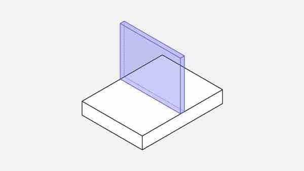
Minimum wall thickness
Recommended: 0.8 mm (metal), 1.5 mm (plastic)
Available: 0.5 mm (metal), 1.0 mm (plastic)
The wall thickness reduces the material’s stiffness, increasing vibration during machining and reducing the achievable precision. Plastics tend to warp (due to residual stress) and soften (due to elevated temperature), so a larger minimum wall thickness is recommended. The above feasible values should be checked on a case-by-case basis.
(5) Hole
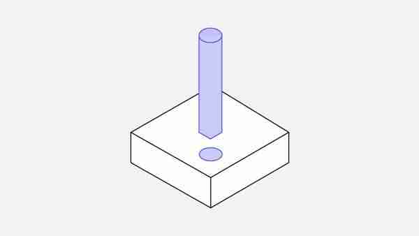
(6). Diameter
Recommended: Standard Drill
Works: Any diameter greater than 1mm
Use a drill or end mill to machine the hole. The dimensions of the drill bits are standardized (metric and imperial units). Reamers and boring tools are used to finish holes that require tight tolerances. Standard diameters are recommended for high-precision holes with diameters less than 20 mm.
(7). Maximum depth
Recommended: 4 times the nominal diameter
Typical value: 10 times the nominal diameter
Available: 40 times the nominal diameter
Holes with non-standard diameters must be machined with end mills. In this case, the maximum cavity depth limit applies and the recommended maximum depth value should be used. Use a special drill (minimum Diameter 3 mm) to make deeper than typical holes. Blind holes machined with a drill have a tapered bottom surface (135-degree angle), while holes machined with an end mill are flat.
There is no particular preference between through holes and blind holes in CNC machining.
(8). Thread
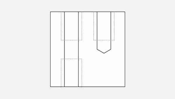
thread size
Minimum: M2
Recommended: M6 or larger
The Thread is cut with a tap, and the external Thread is cut with a die. Taps and dies can be used to cut threads to M2. CNC thread tools are common and favored by machinists because they limit the risk of tap breakage. CNC threading tools can be used to cut threads to M6.
thread length
Minimum: 1.5 times the nominal diameter
Recommended: 3 times the nominal diameter
Most of the load applied to the Thread is carried by the few first teeth (up to 1.5 times the nominal diameter). Therefore a thread 3 times longer than the nominal Diameter is not required.
For threads in blind holes cut with a tap (that is, all threads smaller than M6), add an unthreaded length equal to 1.5 times the nominal diameter at the bottom of the hole. When a CNC threading tool is available (i.e., threads larger than M6), the hole can be threaded over its entire length.
(9). Small function
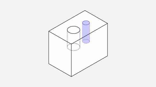
Minimum aperture
Recommended: 2.5 mm (0.1 in.”)
Workable: 0.05 mm (0.005 in. ”)
Most machine shops can precisely machine cavities and holes with tools as small as 2.5 mm (0.1 in) in Diameter. Anything below this limit is considered micromachining. Machining these features requires specialized tools (micro-drills) and expertise, as the physics of the cutting process change with this scale. Therefore, it is recommended to avoid them unless necessary.
tolerance
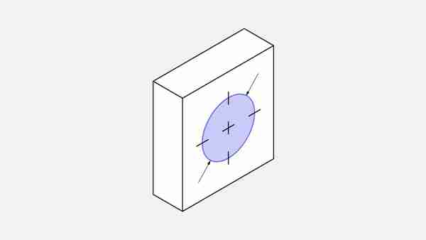
Typical value: +-0.1 mm
Feasible: +-0.02 mm
Our tolerance is 2768 medium or fine. The manufacturing partner will use the selected 2768 grade if no tolerance is specified.
Tolerances define the boundaries of acceptable dimensions. The achievable tolerances vary depending on the basic size and geometry of the part. The above values are reasonable guidelines.
Text and lettering
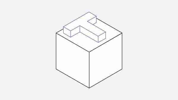
Recommended: Font size 20 (or larger), 5mm lettering
Engraved text is preferable to embossed text because less material is removed. A sans-serif font (such as Arial or Verdana) with a minimum size of -20 is recommended. Many CNC machines have pre-programmed routines for these fonts.
CNC machine setup and part positioning
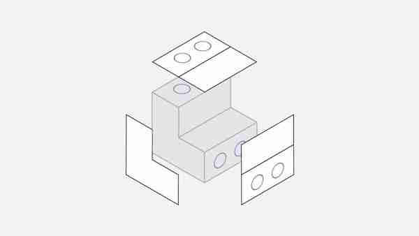
Schematic diagram of parts requiring multiple setups
Tool access is one of the main design limitations of CNC machining. To reach all surfaces of the model, the workpiece must be rotated several times.
Every time the workpiece is rotated, the machine must be recalibrated and a new coordinate system defined.
When designing, it is important to consider machine settings for two reasons:
The total number of machine setups affects the cost. Rotating and realigning parts requires manual work and increases overall machining time. This is usually acceptable if the part needs to be rotated three or four times, but anything over this limit is overkill.
Both features must be machined in the same setup for maximum relative positional accuracy. This is because the new calibration step introduces a small (but non-negligible) error.
What is 5-axis CNC machining?
A 5-axis CNC machine simultaneously moves a cutting tool or part in five axes. Multi-axis CNC machines can manufacture parts with complex geometries because they provide two additional axes of rotation. These machines eliminate the need for multiple machine setups.
What are the advantages and limitations of 5-axis CNC machining?
Five-axis CNC machining always keeps the tool tangent to the cutting surface. Toolpaths can be more complex and efficient, resulting in parts with better surface finishes and shorter machining times.
That said, a 5-axis CNC has its limitations. Basic tool geometry and tool access restrictions still apply (for example, parts with internal geometry cannot be machined).
In addition, the cost of using such a system is higher. CNC Machining Undercuts Undercuts are features that cannot be machined with standard cutting tools because some of their surfaces cannot be directly contacted from above.
There are two main types of undercuts: T-slots and dovetails. Undercuts can be single-sided or double-sided and machined using special tools. T-slot cutting tools are made with horizontal blades attached to a vertical shaft. The width of the undercut can vary from 3mm to 40mm. We recommend using standard sizes (i.e., whole millimeter increments or common fractions of an inch) for widths, as it is likely that suitable tools are already available. For dovetail tools, the angle is the defining feature dimension. Both 45-degree and 60-degree dovetail tools are considered standard. Tools with angles of 5 degrees, 10 degrees, and up to 120 degrees (in 10-degree increments) also exist but are less commonly used.
Undercut Design for CNC Machining
Remember to add enough clearance for the tool when designing parts with undercuts on the inside walls. A good rule of thumb is adding at least four times the undercut depth between the machined wall and any other interior walls.
For standard tools, the typical ratio between cutting Diameter and shaft diameter is 2:1, limiting the depth of cut. Machine shops often make custom undercut tools when non-standard undercuts are required. This will increase delivery time and cost, so please avoid it if possible.