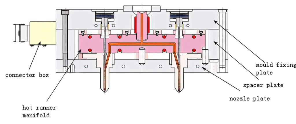
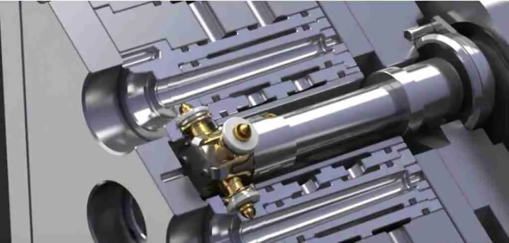
The hot runner is to ensure that the plastic of the runner and gate is kept in a molten state by heating. The hot runner system generally consists of a hot nozzle, a manifold, a temperature control box, and accessories. The hot nozzle generally includes two types: Hot open nozzle and needle valve hot nozzle, because the hot nozzle form directly determines the selection of the hot runner system and the manufacture of the mold, so the hot runner system is often divided into an open hot runner system and a needle valve hot runner system accordingly.

After the plastic mold hot runner system is designed and processed, how to test it? We can test its performance and qualification from the following points:
1. The wiring layout of the hot runner should be reasonable for easy maintenance, and the wiring numbers should correspond one by one.
2. The hot runner should be tested for safety, and the insulation resistance to the ground should be greater than 2MW.
3. The temperature control cabinet, hot nozzle, and hot runner should be standard parts.
4. The main sprue is connected to the hot runner with a thread, and the bottom surface is contacted and sealed.
5. The hot runner is in good contact with the heating plate or rod, the heating plate is fixed with screws or studs, and the surface is well fitted.
6. The J-type thermocouple should be used and matched with the temperature control meter.
7. A thermocouple should control each group of heating elements, and the position of the thermocouple should be reasonably arranged.
8. The nozzle should meet the design requirements.
9. The hot runner should have reliable positioning, at least two positioning pins, or be fixed with screws.
10. A thermal insulation pad should be between the hot runner and the template.
11. The error between the set temperature of the temperature control meter and the actual displayed temperature should be less than ±5°C, and the temperature control should be sensitive.
12. The cavity and the nozzle mounting hole should pass through.
13. The hot runner wiring should be bundled and covered with a pressure plate.
14. There are two sockets of the same specification, which should be marked.
15. The control wire should be sheathed without damage.
16. The temperature control cabinet has a reliable structure, and the screws are not loose.
17. The socket is installed on the bakelite and cannot exceed the maximum size of the template.
18. The wires are not allowed to be exposed outside the mold.
19. All places where the hot runner or stencil contacts the wires should have rounded transitions.
20. Before the template is assembled, all lines should have no open circuit or short circuit.
21. All wiring should be properly connected with good insulation.
22. After the template is mounted and clamped, all circuits should be checked again with a multimeter.

tryout
The purpose of the tryout is to find out the optimized process parameters and mold design. This ensures a stable and uninterrupted mass production environment even if there are changes in materials, machine settings, or the environment, not just to get a good sample. This point is very important.
Trial Step 1. Set the temperature of the barrel
It should be noted here that the initial barrel temperature setting must be based on the material supplier’s recommendations. This is because the same materials of different manufacturers and brands may have considerable differences, and material suppliers often have in-depth research and understanding of their materials. Users can make basic settings according to their recommendations and then make appropriate fine-tuning according to the specific production situation.
In addition, the melt’s actual temperature needs to be measured with a probe. Because the barrel temperature we set often cannot be guaranteed to be 100% consistent with the melt temperature due to differences in the environment, the type and depth of the temperature sensor, etc. Sometimes due to the presence of oil stains or other reasons, the actual temperature of the melt and the set temperature of the barrel is very different (previously, we have had an example of a difference of up to 30°C between the two).
Step 2. Set the temperature of the mold
Likewise, the initial mold temperature setting must also be based on the recommended values provided by the material supplier.
It should be noted that when we say mold temperature, we refer to the temperature of the mold cavity surface, not the temperature displayed on the mold temperature controller. In many cases, the temperature displayed on the mold temperature controller is not consistent with the temperature of the cavity surface due to the environment and improper power selection of the mold temperature controller. Therefore, the temperature of the cavity surface must be measured and recorded before the mold test. At the same time, measuring different positions in the mold cavity is necessary to check whether the temperature at each point is balanced and record the corresponding results to provide reference data for subsequent mold optimization.
Step 3.
According to experience, parameters such as plasticizing amount, the limited value of injection pressure, injection speed, cooling time, and screw speed are initially set and properly optimized.
Step 4. Carry out a filling experiment to find out the transition point.
The switching point refers to the switching point from the injection stage to the holding pressure stage, which can be screw position, filling time and filling pressure, etc. This is one of the most important and basic parameters in the injection molding process. In the actual filling test, the following points need to be observed:
(1) The holding pressure and holding time during the test are usually set to zero;
(2) The product is generally filled to 90%~98%, depending on the wall thickness and the structural design of the mold;
(3) Since the injection speed will affect the position of the inflection point, the inflection point must be reconfirmed every time the injection speed is changed.
Through the filling test, the user can see the flow path of the material in the mold cavity to determine where the mold is prone to air trapping or where the venting needs to be improved.

Step 5. Find out the limit value of injection pressure.
During this process, attention should be paid to the relationship between injection pressure and speed. For hydraulic systems, pressure and speed are interrelated. Therefore, it is impossible to set these two parameters to satisfy the required conditions simultaneously.
The injection pressure set on the screen is the limit value of the actual injection pressure. Therefore, the limit value of the injection pressure should always be higher than the actual injection pressure. Suppose the injection pressure limit is too low so that the actual injection pressure is close to or exceeds the limit value of the injection pressure. In that case, the actual injection speed will automatically decrease due to the power limitation, thus affecting the injection time and molding cycle.
Step 6. Find out the optimized injection speed.
The injection speed referred to here is the injection speed that simultaneously satisfies the filling time as short as possible and the filling pressure as small as possible. During this process, the following points should be noted:
(1) The surface defects of most products, especially those near the gate, are caused by the injection speed.
(2) Multi-stage injection is only used when one injection cannot meet the process requirements, especially in the trial stage.
(3) When the mold is intact, the pressure transfer point is set correctly, and the injection speed is sufficient, the injection speed is not directly related to the generation of flash.
Step 7. Optimize dwell time.
The dwell time is also the condensation time of the gate. Generally, the condensation time of the gate can be determined by weighing to obtain different pressure holding times, and the optimal holding pressure time is the time when the product mold weight reaches the maximum.
Step 8. Optimize other parameters such as holding pressure and clamping force.
Finally, it should be emphasized that the purpose and focus of mold testing are to optimize the mold and process to meet the requirements of mass production, not just to test out good product samples.


