
How to overcome deformation when machining thin-walled parts using CNC turning?
Once you understand lathe machining processes and related technologies, you’ll know that machining thin-walled parts on CNC lathes is quite difficult, especially machining internal holes. This is because during the cutting process, the thin-walled material is easily deformed by the cutting force, resulting in an elliptical shape or a “waist-shaped” structure that is smaller in the middle and larger at both ends. Furthermore, due to poor heat dissipation during machining, the thin-walled outer shell is prone to thermal deformation, leading to dimensional and shape errors. A crucial issue that needs to be addressed is how to reduce the impact of cutting forces on workpiece deformation.
Due to the low thickness and poor rigidity of thin-walled CNC-turned parts, the most significant problem in machining thin-walled products is deformation. Once the deformation exceeds the allowable value, defective parts will be produced. It is important to identify the challenges, causes, and solutions or techniques in the CNC turning process of thin-walled parts. Below are techniques summarized by the Elimold engineering team for overcoming deformation when CNC turning thin-walled parts. If you need to turn thin-walled parts, please contact us.
What is thin-wall processing?
Thin-wall machining refers to the CNC machining of parts with thin cross-sections, no supporting walls, or low structural rigidity. It is not a single machining method, but a machining condition that may occur in milling, turning, drilling, boring, tapping, or finishing operations.
Determining whether a part is thin-walled cannot be based solely on its wall thickness. It also depends on the part’s overall dimensions, wall height, groove depth, unsupported length, and tolerance requirements. For example, machining a 2 mm wall thickness on a small, shallow part may be relatively easy, but machining the same wall thickness on a deep aluminum casing could pose a much higher machining risk.
What are thin-walled turning parts and why are they difficult to machine?
Thin-walled turning parts are typically precision parts, with wall thicknesses much smaller than other dimensions, such as thin-walled tubes, thin-walled pressure vessels, etc. Therefore, machining thin-walled parts on CNC lathes is a challenging problem because they have poor rigidity and strength, making them prone to deformation during machining, resulting in large form and position errors. This increases the difficulty in ensuring part quality. The main challenge in CNC turning thin-walled parts is deformation, which can be caused by cutting forces, leading to an elliptical shape or a shape that is narrow in the middle and wide at both ends. Furthermore, poor heat dissipation due to the outer shell of thin-walled workpieces further contributes to thermal deformation.
1. Thin-walled parts cannot withstand large radial forces, and clamps are generally difficult to install.
2. An unreasonable clamping procedure, improper clamping force, and poor rigidity of thin-walled parts lead to large clamping deformation.
3. The elastic recovery of a workpiece under normal conditions will affect dimensional and shape accuracy.
4. Inappropriate fixture design causes positioning errors.
5. Cutting heat can also affect the control of part dimensional accuracy.
6. Due to the influence of cutting forces, the workpiece is prone to deformation or vibration, resulting in poor surface quality and inaccurate part dimensions.
7. Excessive cutting volume will affect production efficiency.
Summary of the most common phenomena encountered when CNC turning thin-walled parts
In CNC turning, thin-walled parts are frequently machined. When turning thin-walled workpieces, due to their poor rigidity, the deformation of thin-walled workpieces on CNC lathes during the turning process generally exhibits the following phenomena.
1. Due to the thin wall of the workpiece, it is easily deformed under clamping pressure, thus affecting the dimensional and shape accuracy of the workpiece. When using the three-jaw chuck shown in Figure 1 to clamp the workpiece for machining the inner hole, it will slightly deform into a triangle under the clamping force, but a cylindrical hole is obtained after machining. When the jaws are released and the workpiece is removed, the outer circle returns to a cylindrical shape due to elastic recovery, while the inner hole becomes an arc triangle as shown in Figure 2. When measured with an inside micrometer, the diameter D is equal in all directions.
2. Under the action of cutting force (especially radial cutting force), vibration and deformation are easily generated, which affects the dimensional accuracy, shape, positional accuracy and surface roughness of the workpiece.
3. Due to the thinness of the workpiece, the cutting heat can cause thermal deformation, making it difficult to control the workpiece dimensions. For thin-walled metal workpieces with a large coefficient of linear expansion, such as those undergoing continuous semi-finish turning and finish turning in the same apparatus, the thermal deformation caused by cutting heat will greatly affect the dimensional accuracy of the workpiece, and sometimes even cause the workpiece to get stuck in the fixture.
Case studies and techniques for CNC turning thin-walled feature parts
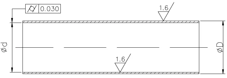
Leveraging the high precision and production efficiency of CNC lathes, and considering the impact of process issues on part machining quality, the deformation problem of thin-walled parts during machining was effectively overcome by optimizing workpiece clamping, tool geometry parameters, and program execution. This ensured machining accuracy and provided a solid foundation and reference for better machining of thin-walled parts in the future. Regardless of the type of CNC lathe used for machining parts, the process must begin with the part drawing. As shown in the figure, machining thin-walled parts is prone to deformation, making clamping inconvenient and machining the parts difficult. Therefore, special thin-walled sleeves and shaft protection are required.
Process Analysis
According to the technical requirements provided in the drawings, the workpiece is machined from seamless steel tubing, with a surface roughness of Ra 1.6μm for both the inner hole and outer wall, achievable by turning. However, the cylindricity of the inner hole is required to be 0.03mm, which is a high requirement for thin-walled parts. In mass production, the process route is roughly as follows: blanking—heat treatment—face turning—outer diameter turning—inner hole turning—quality inspection. The “inner hole machining” process is crucial for quality control. Ignoring the outer diameter and the thin-walled nature of the tubing, it’s difficult to guarantee a 0.03mm cylindricity during inner hole machining.
Key technologies of machining holes
The key technologies for internal turning are solving the rigidity and chip removal problems of the internal turning tool. To increase the rigidity of the internal turning tool, the following measures can be taken:
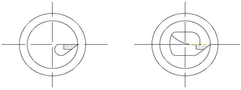
1. Maximize the cross-sectional area of the tool shank. Typically, the tip of an internal turning tool is located on top of the shank, resulting in a relatively small shank cross-sectional area, less than 1/4 of the hole’s cross-sectional area, as shown in the left figure below. If the tip of the internal turning tool is positioned on the center line of the shank, the shank’s cross-sectional area within the hole can be significantly increased, as shown in the right figure below.
2. The tool holder extension length should be 5-8mm longer than the length of the workpiece to increase the rigidity of the tool holder and reduce vibration during the cutting process.
Solving the chip removal problem when turning thin-walled parts
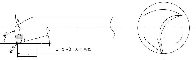
The main control is the direction of the cutting flow. Roughing tools require the chips to flow towards the surface to be machined (front chip removal). For this purpose, an internal turning tool with a positive cutting edge angle is used, as shown in the figure below.
During finish turning, the chip flow should be directed towards the center for chip removal (chip removal from the center of the hole). Therefore, when sharpening the tool, attention should be paid to the grinding direction of the cutting edge. A forward-inclined arc chip removal method should be used, as shown in the figure below. The finish turning tool uses YA6 alloy, currently the M type, which has good bending strength, wear resistance, impact toughness, and resistance to adhesion and temperature with steel.
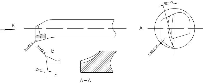
When sharpening, the rake angle should be ground into a circle with an arc angle of 10-15°. The clearance angle should be 0.5-0.8mm away from the wall according to the machining arc (the bottom line of the tool follows the arc). The c cutting edge angle k direction should be §0.5-1, and the finishing edge should be R1-1.5 along the chip cutting edge B point. The secondary clearance angle should be ground to 7-8°. The E inner edge point AA should be ground into a circle to remove chips outward.
Machining methods for thin-walled turned parts
Before machining the aforementioned feature parts using CNC turning technology, a protective shaft must be made. The reasons are as follows:
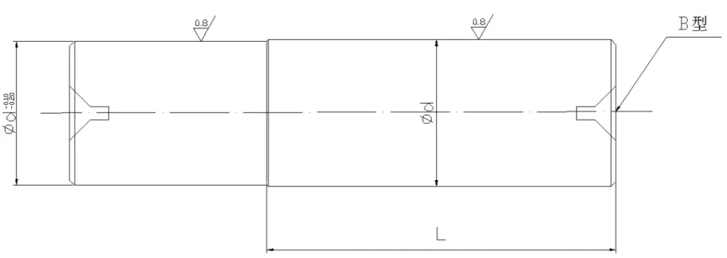
1. The main purpose of the retainer is to fit the machined inner hole of the thin-walled sleeve to its original size, and to fix it with front and rear centers so that the outer diameter can be machined without deformation, thus maintaining the machining quality and accuracy of the outer diameter. Therefore, the machining of the retainer is a key step in the machining process of the thin-walled sleeve. The retainer blank is machined using 45# carbon structural round steel; the end face is machined, and two B-type center holes are drilled at both ends. The outer diameter is rough-machined, leaving a 1mm allowance. After heat treatment and tempering to set the shape, it is then finish-machined, leaving a 0.2mm allowance, and ground. The surface is then re-heat-treated to a hardness of HRC50, and then ground on an external cylindrical grinder to the shape shown in the figure below, achieving the required accuracy. It is then ready for use.
2. To ensure that the workpiece can be processed in one go, leave a clamping position and a cutting allowance on the blank.
3. First, heat-treat and temper the blank to set its shape, achieving a hardness of HRC28-30 (the hardness within the machinable range).
4. The cutting tool is C620. First, the front center is placed into the spindle taper and fixed. To prevent workpiece deformation when clamping thin-walled sleeves, an open-ring thick sleeve is added, as shown in the figure below.
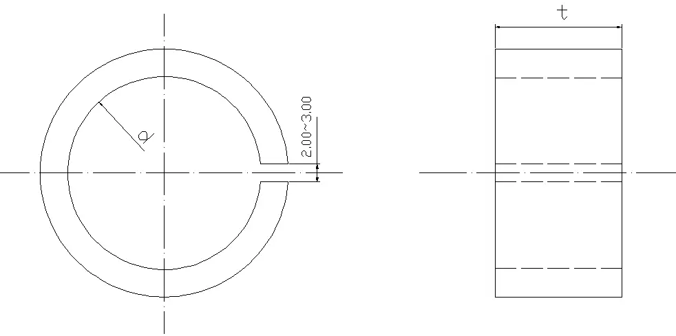
To maintain mass production, one end of the thin-walled sleeve’s outer diameter is machined to a uniform dimension d. The t dimension is used for axial clamping, and the thin-walled sleeves are pressed together to improve quality during internal bore machining and maintain dimensional stability. Considering the heat generated during cutting, the workpiece expansion dimensions are difficult to control. Sufficient cutting fluid needs to be poured in to reduce thermal deformation of the workpiece.
5. Clamp the workpiece securely with an automatic centering three-jaw chuck, turn the end face, and rough turn the inner diameter. Leave a 0.1-0.2mm allowance for finish turning, then change to a finish turning tool to machine the remaining allowance to meet the requirements for the wear shaft’s transition fit and surface finish. Remove the internal turning tool, insert the wear shaft into the front center, and clamp it with the tailstock center according to the length requirements. Change to an external turning tool for rough turning the outer diameter, and then finish turning to meet the drawing requirements. After inspection and approval, cut the workpiece to the required length using a parting tool. To ensure a smooth cut when the workpiece is separated, the cutting edge should be beveled to make the workpiece end face flat; the section of the wear shaft that is ground smaller is to leave a gap during cutting. The wear shaft is designed to reduce workpiece deformation, prevent vibration, and prevent damage from falling during cutting.
Elimold’s engineering team provides solutions for CNC turning of thin-walled parts.
We know how CNC lathes process deformed thin-walled workpieces, so how should we deal with the deformation of thin-walled workpieces on CNC lathes? Here are some solutions.
1. The workpiece is divided into roughing and finishing stages. During roughing, the cutting allowance is relatively large, the clamping force is slightly larger, and the deformation is correspondingly larger. During finishing, the clamping force can be slightly smaller, which helps to prevent deformation and also eliminates the deformation caused by excessive cutting force during roughing.
2. When precision machining thin-walled workpieces by making reasonable use of geometric parameters, high rigidity is required, the finishing blade should not be too long (generally 0.2-0.3mm), and the cutting edge should be sharp.
3. Increase the clamping contact surface. Use slit sleeves or special soft jaws. Enlarging the contact surface allows the clamping force to be evenly distributed on the workpiece, making it less prone to deformation during clamping.
4. Pour in the cutting fluid thoroughly. By fully pouring in the cutting fluid, the cutting temperature is reduced, thus minimizing thermal deformation of the workpiece.
5. Add process ribs. Some thin-walled workpieces have several specially made process ribs at the clamping position to enhance the rigidity of this area, so that the clamping force acts on the process ribs, thereby reducing workpiece deformation. After machining, remove the process ribs.
6. When using axial clamping, the fixing device should be for machined thin-walled workpieces. Radial clamping should be avoided as much as possible; the axial clamping method shown in Figure 4 is preferred. The workpiece is axially clamped by the end face of the axial clamping sleeve (threaded sleeve). Because the clamping force F is distributed along the axial direction of the workpiece, the axial stiffness of the workpiece is large, and clamping deformation is not easily generated.
Techniques for improving CNC turning of thin-walled parts
Based on the problems existing in CNC turning of thin-walled parts, the selection of machining equipment, processes, fixture design and settings should be fully considered, and then the best conditions should be selected.
Make the clamping force as uniform as possible
For general parts machining, a three-jaw chuck is sufficient for positioning and clamping. However, for thin-walled parts, high precision and precise form and position errors are required. Improper clamping and positioning can lead to deformation and affect part quality. Therefore, increasing the number of clamping points and expanding the contact area between the jaws and the workpiece are effective measures to reduce deformation during the turning of thin-walled parts.
Change positioning and clamping design
During turning, the workpiece is positioned by its outer diameter or inner hole, using a three-point clamping mechanism. To reduce the impact of circumferential (radial) clamping on workpiece dimensional accuracy, this can be achieved by changing the clamping method, specifically replacing radial clamping with end-face clamping. This avoids workpiece deformation and increases cutting resistance by increasing end-face friction.
Adjust machining parameters to reduce the influence of cutting forces
We know that excessive cutting forces can also cause localized deformation in CNC-machined thin-walled parts. Workpiece deformation caused by cutting forces can be controlled by appropriately selecting cutting parameters and tool geometry. High-speed machining is an effective method. Higher spindle speeds not only help reduce cutting forces but also remove most of the cutting heat from the workpiece, reducing the impact of cutting heat on the part. Appropriate tool angles can also alter the cutting force state. Generally, not only reducing the depth of cut but also a larger tool cutting edge angle, a slightly larger rake angle, and a smaller tool tip radius helps reduce cutting forces.
CNC turning of thin-walled parts adds auxiliary support.
When machining thin-walled parts with high internal bore precision requirements, auxiliary supports can be used to increase the rigidity of the workpiece. Although the wall thickness may seem like a minor design difference, thin-walled parts are very sensitive to cutting forces, temperature changes, and internal material stresses.
Choosing to collaborate with Elimold on a project to machine thin-walled parts
Elimold’s CNC turning services can machine parts up to 98 inches in diameter with straightness tolerances of +/- 0.001 inches. Processes include milling, turning, drilling, boring, threading, tapping, forming, knurling, countersinking, counterboring, reaming, and laser cutting. For secondary services, we also offer assembly, centerless grinding, heat treatment, electroplating, and welding. We turn up to 50,000 thin-walled parts for prototyping and small-batch production, suitable for fluid power, pneumatic, hydraulic, and various valve products. We currently serve companies in the aerospace, aircraft, military, medical, and defense industries worldwide. When you need to turn thin-walled parts, contact Elimold. We will work with you to develop a strategy and provide the most cost-effective service to help you achieve your goals. Contact us ([email protected]) directly for your new projects.
in conclusion
above methods , summarized by the Elimold engineering team , primarily involve adding a sleeve when machining thin-walled parts . This solves the problem of deformation or dimensional and shape errors that prevent the parts from meeting requirements. Practice has proven that this method offers high machining efficiency, ease of operation, and suitability for machining longer thin-walled parts. Dimensions are easy to control, and the parts can be completed in one go, making it practical for mass production. If you have a need for large-volume CNC machining of thin-walled parts, please contact the Elimold team for assistance.